Concept:
Game controllers are frequently criticized for their imprecise controls, which put them at a competitive disadvantage compared to a mouse and keyboard. However, the form factor allows for more relaxed and comfortable use, and some applications, for example racing games, benefit greatly from the additional granular inputs like triggers.
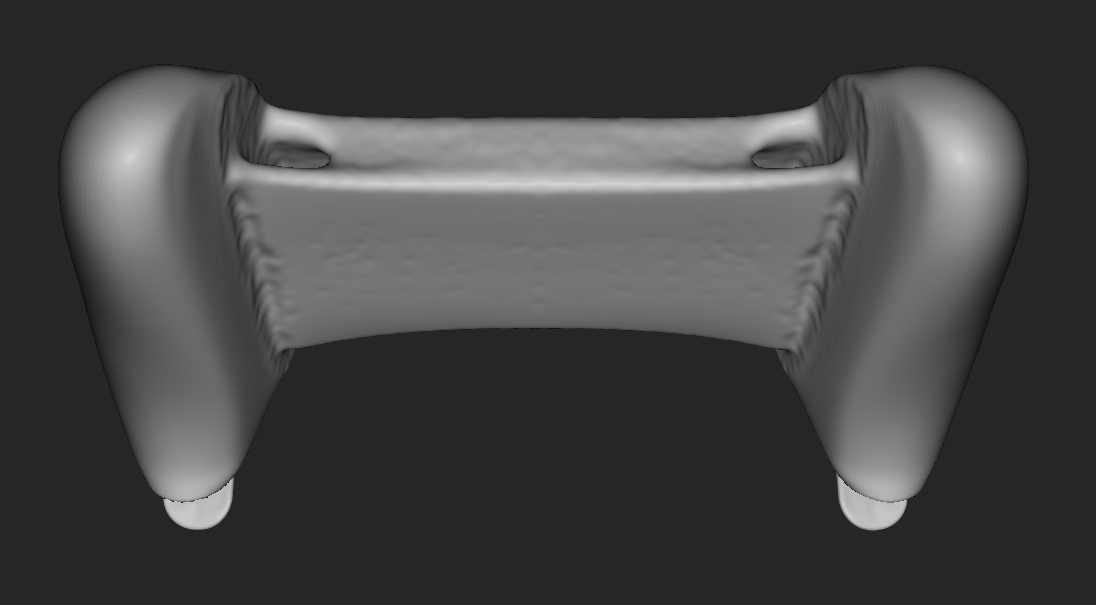
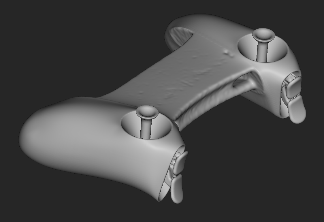
In order to reduce the downsides of the small input area and maximize the advantages of the format, I set about conceptualizing a controller with the most granular inputs possible, including deep inset joysticks and long travel triggers. All other buttons will be moved to the interior of the grips, preventing the user from having to remove their fingers from the joysticks during use.
Because this product will be held for a long period of time, and likely subjected to significant abuse, it was important to make sure the structure was as well suited to these conflicting purposes as possible. To accomplish this, I used nTopology to minimize the weight and structural compliance of the central structure of the body, as well as both pairs of triggers. The procedure and lessons learned from this project are detailed below.
Set Up:
Using surface modeling tools in Fusion 360, I created a model with the maximum acceptable dimensions, shown above.
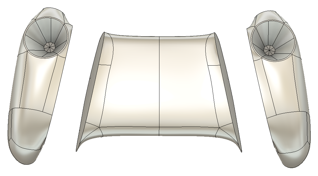
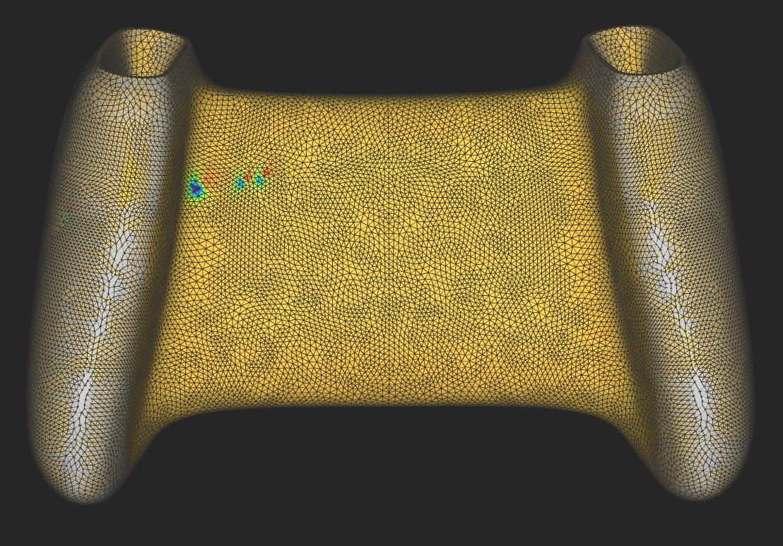
After I was happy with the overall shape, I sliced the model into three sections: The central span, which is the section to be optimized, and the two handles, which will remain mostly unchanged. After importing these sections into nTopology, I remeshed the parts, as the STL meshes were very inconsistent and low quality. To prepare for Topology optimization, I also ran a static analysis on the part; this revealed some small perturbations on the bottom of the center, but these did not show up in the final optimization.
Initial Results:
"Room for Improvement"
The first optimization was done using a central displacement restraint and forces acting on either side through the handles, which resulted in far too much material gathering around the middle. The part also has clear asymmetry, with more material deposited on the right side; this issue persisted despite the later implementation of a symmetry constraint.
Another issue that arose early on was that of the final smoothing step removing most of the connection between the center and handles, making them appear as disconnected parts and weakening the structure. This was due to the wall which was created to handle the force being too thin for the smoothing algorithm.
Revision:
The boundary conditions were revised to place a force on one handle, and a displacement restraint on the other. This decreased the number of forces, and more importantly made the simulation much more realistic. The mesh was made symmetrical by importing half of the body and then mirroring it after remeshing, as the symmetry constraint was inconsistent in its efficacy. Finally, the edges of the center were extended slightly, and a passive condition was applied on the overlapping area, preventing the optimization from removing any of this material. These areas were also used to apply forces and displacement restraints.
Individual Loads:
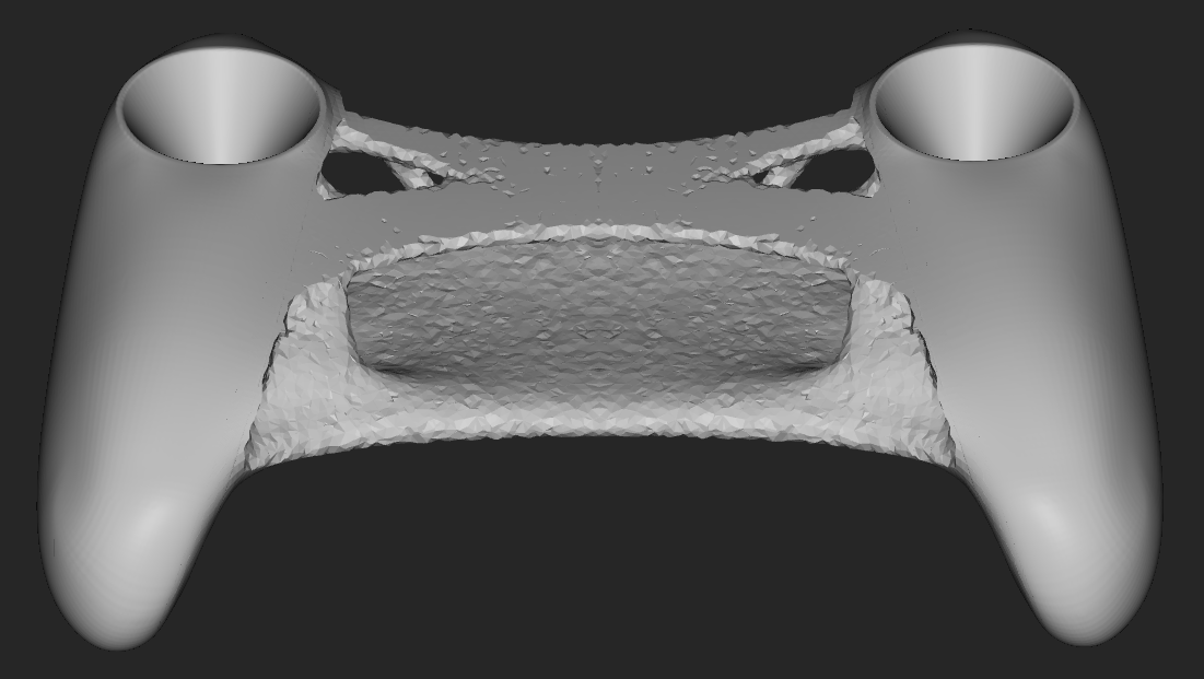
Compression / Expansion
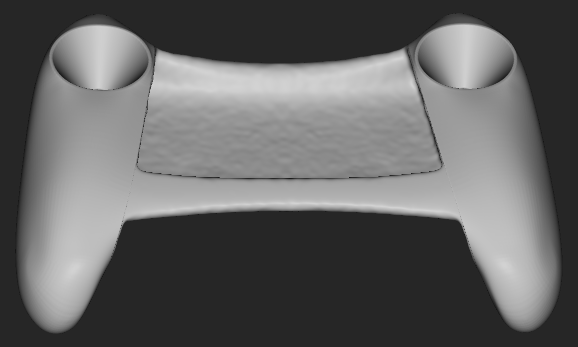
Horizontal Shear
Vertical Shear
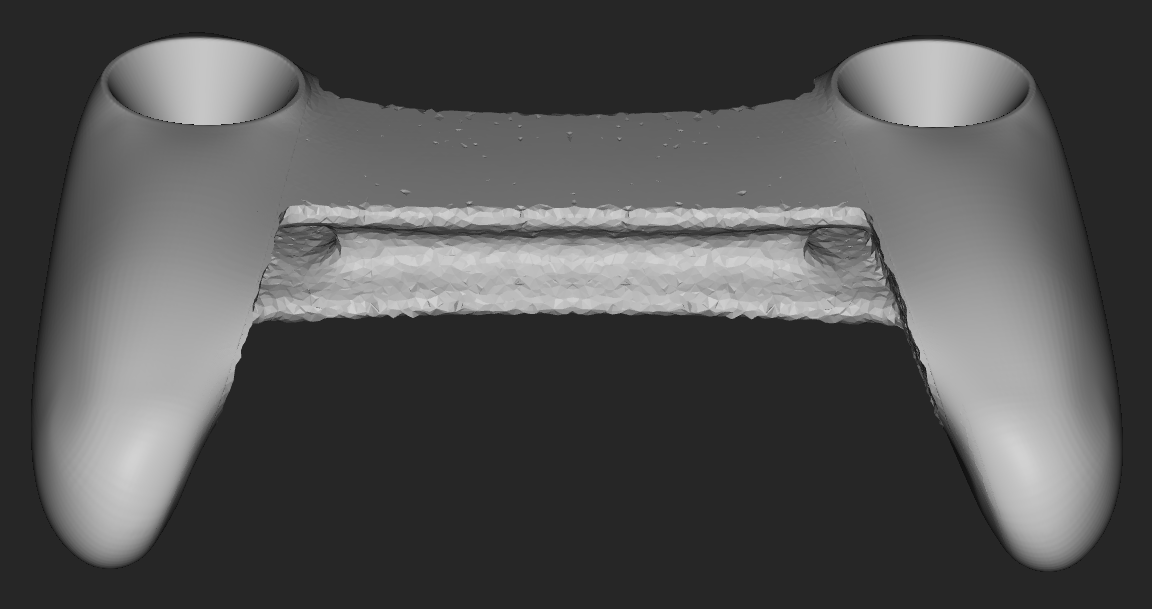
I first investigated the design space for single load cases, namely compression, vertical shear, and horizontal shear. all simulations were completed using a maximum final volume of 40% of the initial body. I found that, surprisingly, the generated results were identical for a reversed force. This indicates there are likely some inaccuracies in the optimization algorithm, as this obviously does not hold true in many real world situations. The compressive case has a triangular structure at each end of the top, with several small connecting elements, with an overall look that we have come to expect from topology optimization. On the other hand, both shear conditions result in a much simpler shape that roughly approximates an I-beam,
Combined Loads:
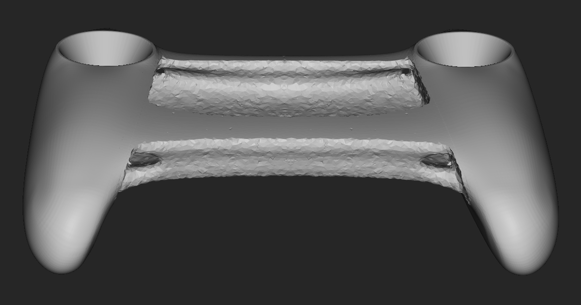
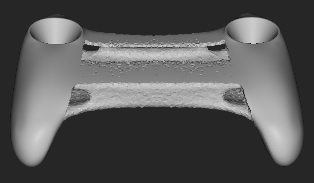
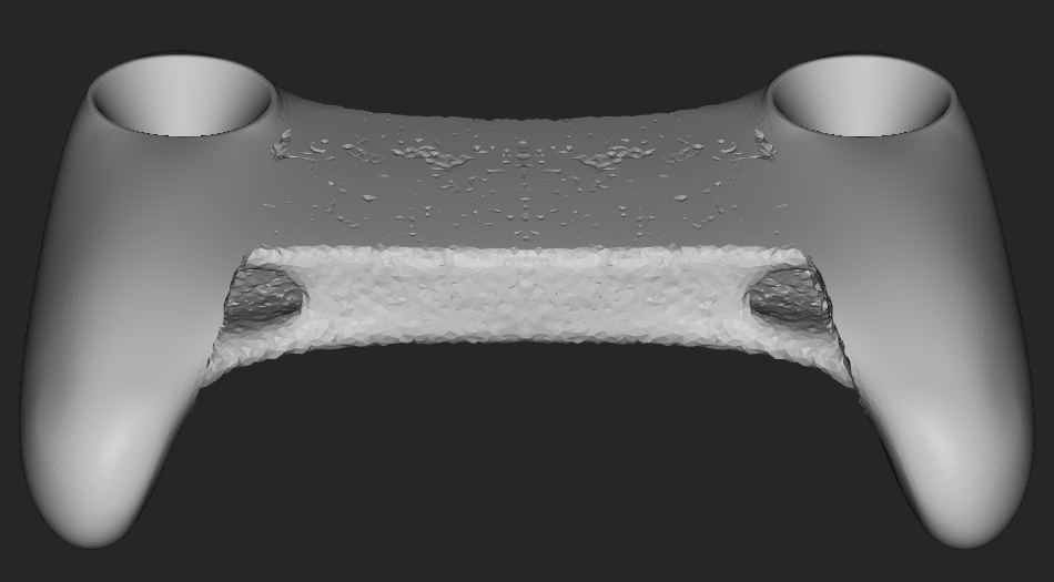
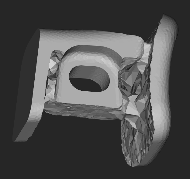
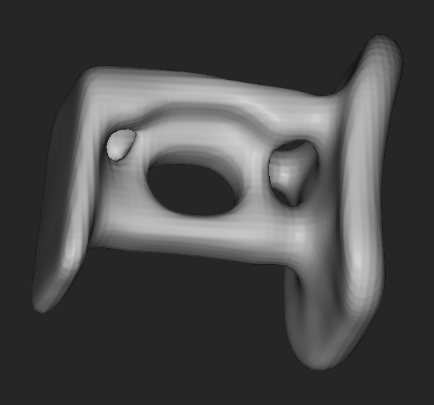
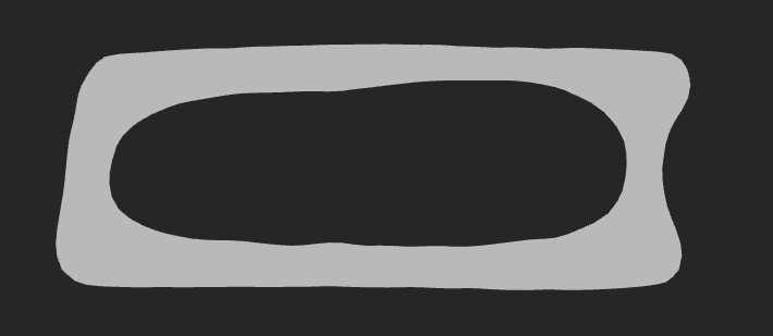
Combining all three loading conditions, the solution space narrowed to the geometries shown above, where the center approximates a shell, and holes consistently appear at each of the four corners. The bottom surface was almost always fully filled, while the center of the top was sometimes removed depending on the relative magnitudes of the loading conditions. Beyond the holes at each corner, this is a fairly unremarkable result, and could likely be accomplished with variable shell thickness in a more aesthetically pleasing but somewhat less optimal manner.
Additional Optimization: Trigger Assembly
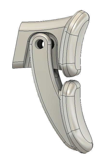
Trigger Assembly
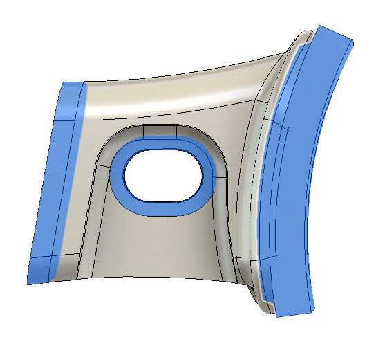
Upper Trigger Passive Regions
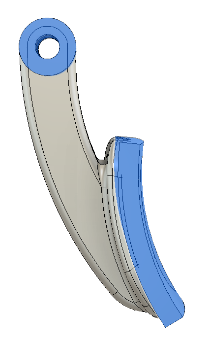
Lower Trigger Passive Regions
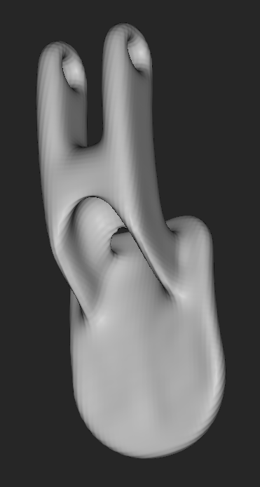
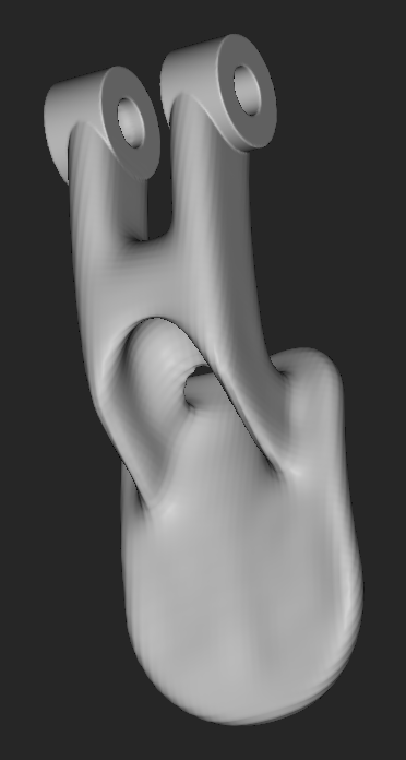
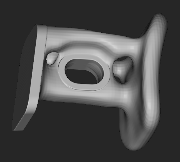
In addition to the body, I also optimized the geometry of both triggers. The upper trigger was particularly interesting, as it had a third interfacing surface in the form of the guide slot in the center. Shown above is the initial assembly, as well as the passive regions for each part individually.
Optimization workflow:
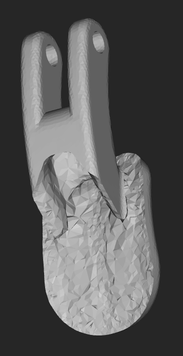
Optimization Output
Smoothed Body
Union with interfacing features
Optimization Output
Smoothed Body
Union with interfacing features
Both parts used a volume fraction of 60%, to account for the increased percentage of passive regions. The lower trigger was fixed at the rear plane, and evaluated using 3 separate loading conditions, including two forces roughly normal to the surface and a transverse force. The upper trigger was subject to four conditions, including a normal pressure, a transverse horizontal force, and two sets of opposing vertical forces applied to the central hole and the front face. Because nTopology currently only supports a single set of fixed regions, these last two tests retained the fixed rear these last conditions were not fully representative of a real life loading condition.
Final Trigger Assembly
Final Design:
Central Cross Section
Road Blocks:
While I attempted to run static simulations on all of the output bodies, no matter what I tried I could not produce a working mesh from the smoothed output. I also attempted to create a variable shell of the central section using the previously completed static analysis, but while I was able to get the block to successfully compile, it did not appear to generate a result, so I was likewise unable to complete this part in time.
Initially I wanted to create a conformal mesh on the handles in order to reduce weight and heat buildup, as well as increase friction on the surface. However, after further investigation I found that this required inputting a pressure field, and without valid data to populate this field any resultant optimization would be a rough estimate at best.
Lessons Learned:
nTopology is fantastic and incredibly powerful software, with several bugs and growing issues. In addition to the above mentioned compilation related errors, the current limitation of a single fixed condition for each topology optimization has the potential to be a major bottleneck in more complex scenarios. The lack of any difference between opposite loading conditions is also a cause for concern, as this would seem to be fundamental to the functionality of the software, and I would love to know more about the underlying reasons for this behavior.
Not all generated geometry is complex, and some loading cases do not necessitate advanced optimization tools. Unfortunately, optimal results are often highly unpredictable, so being able to use methods like these remains important for many seemingly benign scenarios, if only for checking and developing an intuition for similar problems. To the same end, despite the limited time and shortcomings of the software, I feel I have a far better understanding of what optimality looks like for the classic minimal weight/structural compliance optimization explored above.
Next Steps:
In the future I will try exporting these results to other software - likely ANSYS - to complete the structural analysis of each generated part, and assess the quality of the result and any potential concerns. I will also continue to use nTopology with this and other projects, including attempting to fix the variable shell thickness and post generation analysis, and further exploring the generation of optimized conformal meshes.
